
Free Preview
Industrial AC Motor Wiring & Drive Simulator
The Industrial AC Motor Wiring Simulator provides an advanced vector tracking environment designed to model both heavy industrial 3-phase networks and residential single-phase induction...
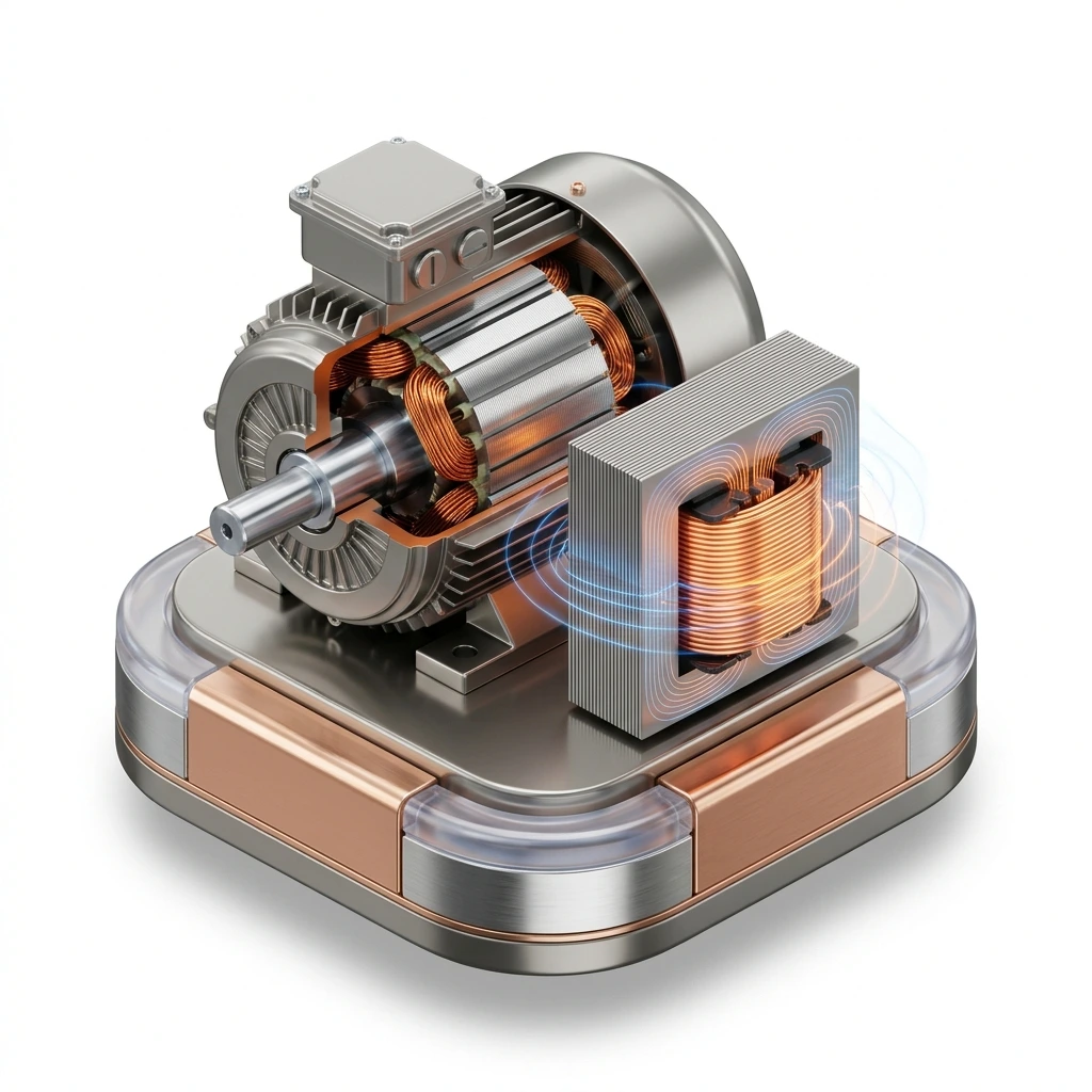
The Industrial AC Motor Wiring Simulator provides an advanced vector tracking environment designed to model both heavy industrial 3-phase networks and residential single-phase induction machines. The trainer features twin functional divisions: a 3-Phase Direct-On-Line (DOL) Starter module complete with a Single Phase Preventer (SPP) and Thermal Overload Relays (OLR), and a 1-Phase Capacitor-Start circuit loop equipped with an automated centrifugal switch mechanism.
The software runs line-to-line network validation checks, simulating operational motor slip curves, induction hum profiles, transient inrush currents, and phase imbalance faults inside a completely safe digital environment.
Industrial Starter Topology: To construct, wire, and evaluate standard Direct-On-Line (DOL) power and control interlocking circuits.
Safety Relay Interlocking: To investigate how protective components (Thermal Overload Relays and Single Phase Preventers) trap faults to safeguard heavy machinery.
Single-Phase Starting Physics: To map out how auxiliary windings and start capacitors provide the necessary phase shift to generate starting torque in single-phase systems.
Dynamic Schematic Workspace: A vector stage supporting sub-terminal line snaps, viewport coordinate scaling, and customizable wire tracing loops.
Molded-Case Switchgear Block: Industrial component footprints for 3-pole MCCBs, magnetic contactors (K1), thermal relays, and dual-button station pods.
Multi-Winding Induction Actuators: Automated machinery models featuring real-time rotor blur animations, centrifugal switch cutouts, and horse-power overrides.
Digital Telemetry LCD Panel: High-contrast instrumentation display tracing live Line Voltages, phase load currents, rotor RPM, and instantaneous torque (Nm).
Real-Time Event Logger: A diagnostic tracking log documenting phase updates, loop connections, and breaker trip exceptions.
Phase 1: Wiring a 3-Phase Direct-On-Line (DOL) Starter LoopEnsure Lab 1: 3-Phase DOL Starter is active in the lab selector. Set your motor rating to $5\text{ HP}$.Click Start Wiring Guide to load the predefined element matrix, or click Auto-Wire to immediately review a completed schematic mapping.If wiring manually, enter Wire mode, select Phase R (Red), and complete the main high-power path: connect MCCB out ($T1$) $\rightarrow$ Contactor input ($L1$) $\rightarrow$ OLR input ($L1$) $\rightarrow$ Motor terminal ($U1$).Duplicate this path for Phase Y (Yellow) and Phase B (Blue) using the respective line colors across terminals $2$ and $3$, routing lines into motor endpoints $V1$ and $W1$.Connect the control circuit loop using Control (Orange) wire: feed Phase R out into the Single Phase Preventer (SPP) common terminal $15$, loop out from the normally-open (NO) terminal $18$ into the OLR NC auxiliary contact 95, and route out from contact $96$ into the Stop Button NC contact.Wire the Stop Button output to the Start Button NO contact, then hook the Start output directly to the Contactor Coil terminal $A1$. Bridge the contactor coil return ($A2$) back to Phase Y to supply a $415\text{V}$ loop.Connect auxiliary terminals $13$ and $14$ in parallel across the Start button contacts to establish a latching latch circuit.Switch the main supply panel to ON. Turn the cursor tool to Interact mode, click the MCCB lever to close the breaker, then click and hold the green START button.Observation: The contactor plunges downward, the motor cylinder blurs as it ramps up to $1440\text{ RPM}$, the LCD telemetry panels light up, and a deep magnetic stator hum hums over your audio channel.Phase 2: Simulating and Managing a Single-Phasing FaultWith the 3-phase motor spinning at full speed, enter Select mode. Right-click on the Phase B (Blue) wire running between the MCCB and the contactor to delete it.Observation: The event log flags an asymmetry alert. Because the SPP control protection is wired in, its internal relay opens instantly, cutting power to the contactor coil ($A1$) and dropping the main contacts open to shut down the machine safely before single-phasing currents melt the windings.Re-enter Wire mode, fix the broken connection line, clear your event console log, and cycle the control station to verify stable operation.
No figures available for this experiment.
Initializing secure sandbox environment & decrypting simulation...