
Free Preview
Basic House Wiring Simulator
The Basic House Wiring Simulator provides an interactive virtual laboratory for modeling single-phase residential electrical installations. Operating on a strict node-graph logic framew...
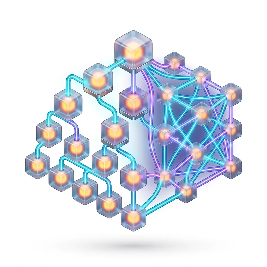
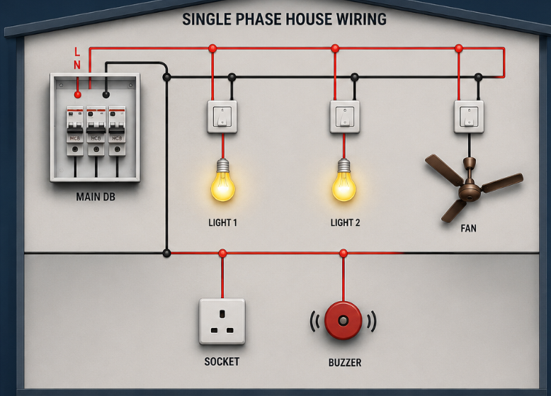
The Basic House Wiring Simulator provides an interactive virtual laboratory for modeling single-phase residential electrical installations. Operating on a strict node-graph logic framework, the trainer allows students to build safety-compliant electrical networks connecting a Main Distribution Board (DB) directly to standard household utilities—such as lights, switches, ceiling fans, sockets, and buzzers. The environment includes physics checking for structural short circuits and ground-to-phase faults, automatically triggering safety breaker trips (MCBs) and realistic hardware component damage when code rules are violated.
- Wiring Code Mastery: To implement standardized single-phase wiring patterns utilizing appropriate phase (Live/Line), Neutral, and Earth conductors.
- Control Loop Topology: To arrange operational circuit pathways that ensure all control elements (switches) isolate the Phase line prior to the consumer load.
- Fault Tracing & Diagnostics: To analyze circuit graphs to prevent, trap, and isolate short circuits and earth leakage exceptions.
- Instrument Operation: To utilize localized tools like neon diagnostic testers to map electrical potential lines.
- Grid-Snapped Wiring Canvas: An infinite workspace featuring an adaptive coordinate alignment grid, 50x zoom, and vector path routing.
- Standard Service Distribution Board: A main panel component providing fixed access nodes for Live ($L$), Neutral ($N$), and Earth ($E$) lines at $230 ext{V} ~ 50 ext{Hz}$.
- Modular Consumer Inventory: Component structures including 1-way switches, multi-way staircase links, sockets, inductive fans, and fluorescent loads.
- Synchronized Diagnostics Log: An active diagnostic readout tracking phase continuity and the count of active consumers.
- Interactive Step-by-Step Guide: An integrated guidance overlay assisting students through structural terminal connections.
Phase 1: Wiring a Basic Single-Switch Light Loop
- Toggle the helper module to engage the Interactive Guide or initialize the project canvas in Select Mode.
- Drag a 1-Way Switch and a standard Light Bulb fixture from the toolbox onto the central structural board workspace.
- Access the cursor toolbar and switch your active utility tool to Draw Wire. Select Phase (Red) from the wire color array.
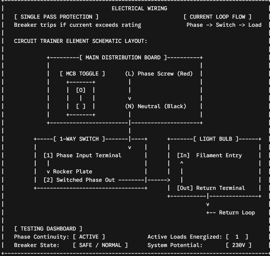
- Click down on the $L$ (Phase) terminal screw on the main DB board, trace your pointer path toward the switch base, and snap the connection to the input screw (Terminal 1).
- Draw an uninterrupted red jumper line linking the switch output screw (Terminal 2) directly to the In screw node of the target Light Bulb.
- Swap your active conductor wire style to Neutral (Black). Route a return line from the bulb's Out screw terminal back to the shared $N$ (Neutral) busbar screw on the main DB board.
- Click down on the Main Breaker (MCB) switch toggle. Look at the Diagnostics Log to confirm the status panel registers NORMAL mode.
- Switch your cursor tool over to Interact mode. Click directly on the face of the 1-way switch to close the contact loop.
Observation: The bulb instantly lights up, a low-frequency $60 ext{Hz}$.
Initializing secure sandbox environment & decrypting simulation...