
Free Preview
Pneumatic Circuit Trainer Simulator
The Pneumatic Circuit Trainer Simulator is a digital training interface designed to model, test, and troubleshoot industrial fluid power configurations. It provides students with hands-...
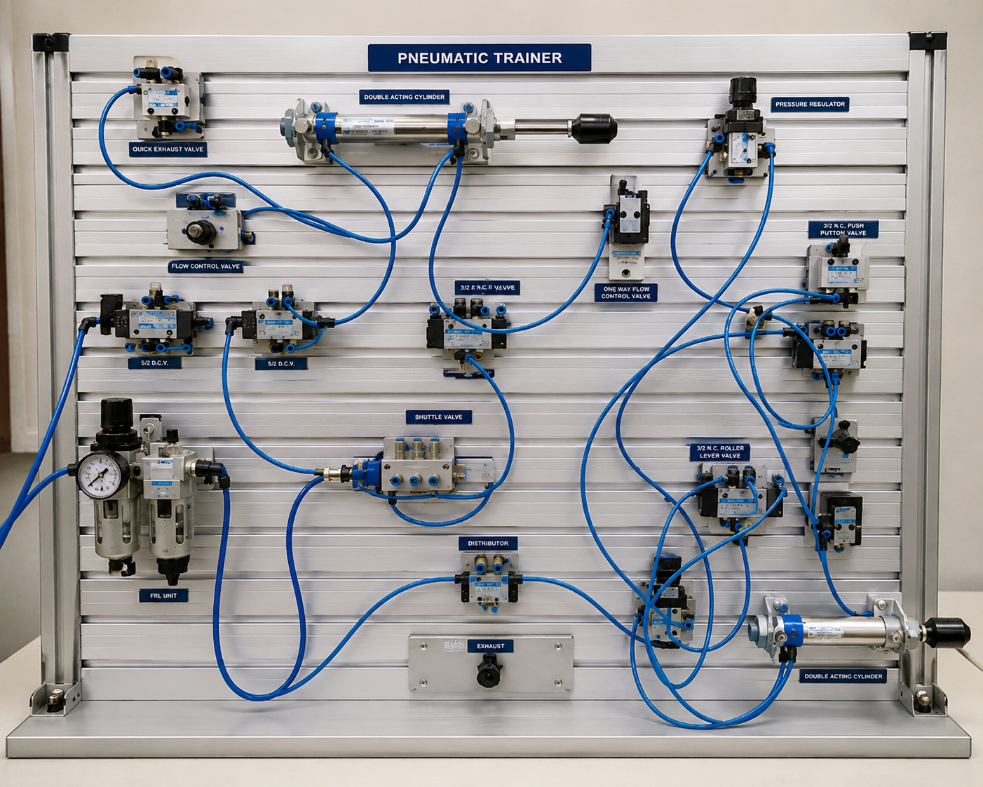
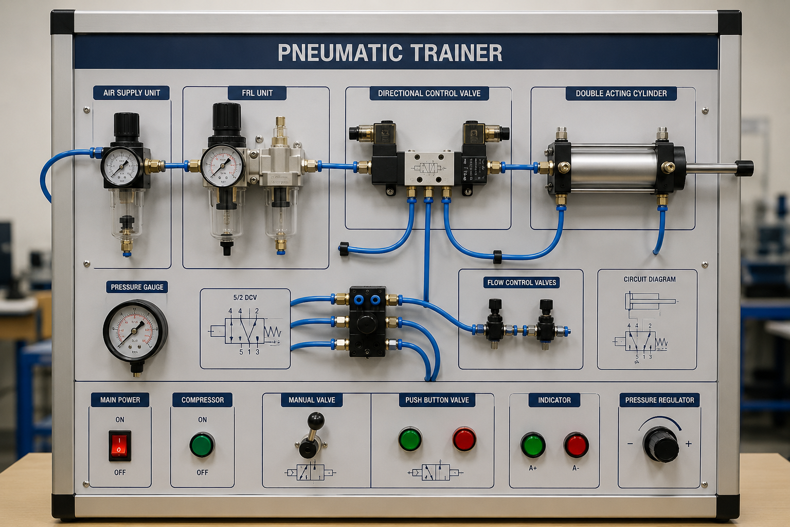
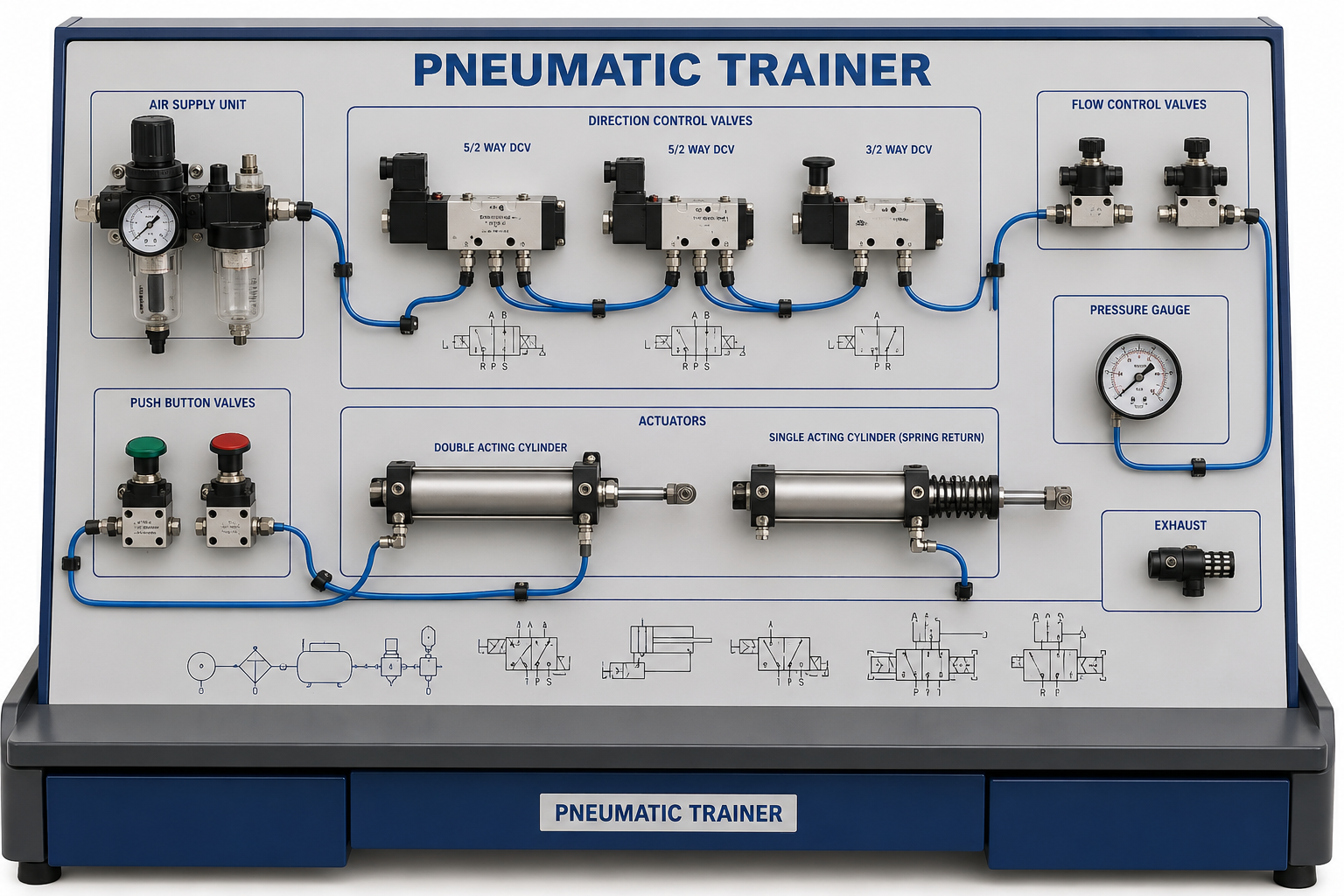
The Pneumatic Circuit Trainer Simulator is a digital training interface designed to model, test, and troubleshoot industrial fluid power configurations. It provides students with hands-on experience in building layouts using a comprehensive database of physical and structural modules, including air supply packs, directional control valves (3/2 and 5/2 DCVs), flow throttles, and single/double-acting cylinders. By combining real-time pressure-drop tracking with interactive component mechanics, the simulator allows students to evaluate circuit behaviors safely, without the risk of high-pressure hardware damage.
- Circuit Topology Design: To design, arrange, and wire structural fluid circuits by connecting source nodes directly to working actuators.
- Valving Architecture Identification: To differentiate between 3/2 and 5/2 Directional Control Valves, analyzing how spool configurations alter physical airflow paths.
- ISO Symbol Interpretation: To interpret abstract ISO standard fluid symbols alongside real-time 3D rendered hardware assemblies.
- Fault Tracing & Maintenance: To diagnose and repair structural errors, such as component leaks, burst tubes, and mechanical piston jams.
Materials Provided Interactive Node Canvas: A flexible workspace with support for multi-axis panning, scaling, and line routing.
Component Assembly Inventory: Pre-calibrated hardware models covering compressors, FRL units, check valves, and logic elements.
Mechanical Animation Monitor: A cross-sectional view tracking live piston extensions, spring deflections, and internal air pressures.
Dynamic Bourdon Gauge: A centralized dial readout tracking line changes with realistic needle physics.
Fault Injection Console: An administrative system menu used to simulate industrial system failure modes.
Phase 1: Operating a Double-Acting Cylinder (DAC) CircuitSelect Double Acting Cylinder Control from the preset drop-down menu in the configuration block.Click the Air Supply toggle to switch the compressor state to ON. Use the slider tool to verify that the target pressure settles at a safe baseline of $6.2 \text{ bar}$.Observation: Look closely at the circuit pipelines. Notice how the default connection line changes color to bright emerald green along the active high-pressure paths, while low-pressure exhaust lines stay blue.Open the Circuit Control Panel on the right side. Push the directional control lever over to Position 2 (Retract).Animation Analysis: Watch the Animation View pane closely. Observe how the air shifts to fill the front rod-end cylinder port, pushing the piston head backward into a retracted state.Phase 2: Stress Testing & Pruning Tube BurstsIncrease the System Pressure Slider up past $9.0 \text{ bar}$, forcing the compressor past its typical safe limits.Lower the Tube Burst Threshold slider to $7.5 \text{ bar}$ to simulate aged or worn system piping.Observation: Watch the active workspace canvas. You will see warning flags popup and lines turn red as the excess pressure causes supply tubes to rupture or blow out.Look at the Pressure Gauge to trace the immediate localized pressure drop caused by the line leak.Right-click the damaged pipe segment to identify the exact error code, or click Repair All Damages to restore the system to peak working condition.
Initializing secure sandbox environment & decrypting simulation...