
Free Preview
Mechanical Vibrations, Modal Analysis & Industrial Instrumentation
The VibroLab Pro | Mechanical Vibrations & Modal Analysis is an interactive simulation workbench designed to teach the behavior of oscillating mechanical systems, resonant modal sha...
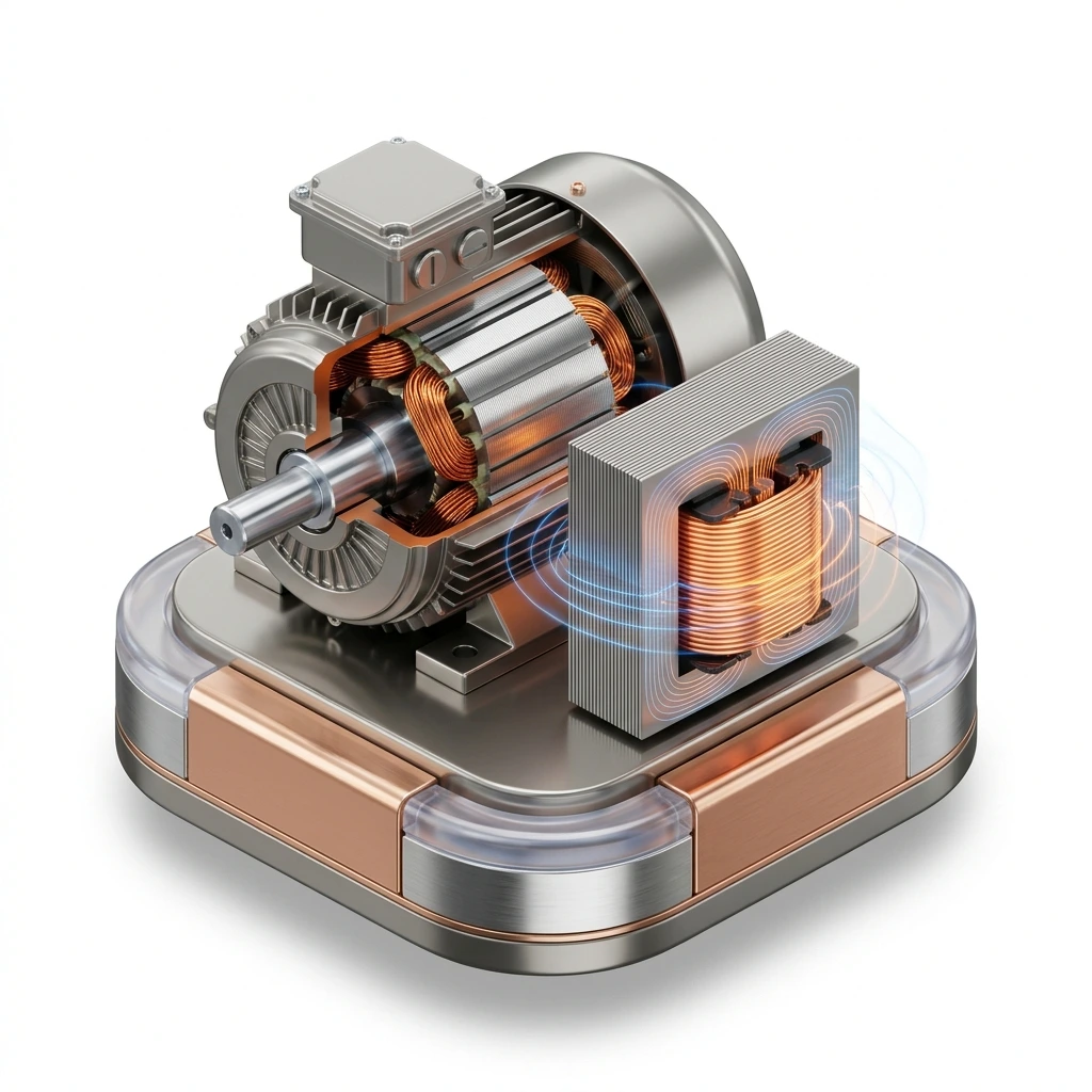
The VibroLab Pro | Mechanical Vibrations & Modal Analysis is an interactive simulation workbench designed to teach the behavior of oscillating mechanical systems, resonant modal shapes, and the engineering of vibration isolation and mitigation
Continuous Beam Modal Analysis: Determine bending shapes, compare cantilever properties (Steel, Aluminum, Titanium), and inspect non-moving nodal points where deflection drops to zero. Passive Mass Isolation & Anti-Resonance: Tune a secondary absorber ($k_2/m_2$) to match machine excitation ($\omega$), generating an out-of-phase force that stops the primary mass ($X_1 = 0$).
ISO 10816 Severity Gauging: Measure RMS velocity ($v_{\text{rms}}$) across varying forcing conditions to determine equipment safety zones. Fourier & Bode Analysis: Correlate time waveforms with peak spectral frequencies and transmissibility curves using DSA instrumentation.
Active Apparatus Testbed: Mechanical cantilever clamping rig, vice vice stand, electrodynamic shaker, 2-DOF mass-spring-damper, Jeffcott rotor with shaft probes, and modal impact hammer. Signal Instrumentation: Laser Doppler Vibrometer (LDV), strain gauges, piezo accelerometers, Eddy-current proximity probes, and digital scope/FFT analyzer. Reagents & Alloys: Structural Steel, Aircraft Aluminum 7075-T6, and Titanium Ti-6Al-4V. Data Deck: Sliders for Beam Length ($0.4\text{--}2.0\text{ m}$), Forcing Frequency ($5\text{--}350\text{ rad/s}$), Stiffness ($20\text{--}800\text{ N/m}$), Damping, Rotor Speed, and Eccentricity ($10\text{--}200\text{ mm}$).
Step 1: Modal Analysis of a Continuous Cantilever Load Standard Rig and choose Beam Modal. Set excitation to Harmonic and toggle through Mode 1 to Mode 4 bending shapes. Observation: Bending shapes show distinct zero-amplitude nodes (Mode 2 has one node, Mode 3 has two, Mode 4 has three) while the accelerometer traces the motion. Step 2: Tuned Vibration Absorber (TVA) Anti-Resonance TuningSwitch to Tuned Absorber module and set excitation to $10\text{ rad/s}$ to induce resonance on the machine $M_1$ ($v_{\text{rms}}$ spikes into Danger Zone D). Adjust Absorber Stiffness $k_2$ and click Auto-Tune TVA.
Step 3: Finding Rotor Critical SpeedsSwitch to Rotor Whirling and increase speed towards $10\text{ rad/s}$.
Step 4: Observing Supercritical Self-CenteringSet speed above $30.0\text{ rad/s}$.
Step 5: Impact Hammer & Signal Spectrum Testing Run Harmonic or trigger Tap Impact.View the FFT Spectrum or Bode Response on the DSA to inspect natural frequencies, peak resonance, and attenuation
No figures available for this experiment.
Initializing secure sandbox environment & decrypting simulation...